Optimizations: Efficiency, Consumption and Heating Curve
For efficient operation and a long service life of the heat pump, there are several optimizations that you can carry out yourself. These optimizations depend on local conditions and personal preferences and therefore differ from heat pump to heat pump. Some of these optimizations—from simple to somewhat more complex—are listed below.
The following applies in principle to efficient operation:
The lower the temperature (difference), the lower the energy consumption!
Rule of thumb: each additional degree increases energy consumption by approx. 2.5% [Source]
Domestic Hot Water Production
10–20% of the heat pump’s annual energy demand is used for domestic hot water production. Therefore, optimizations can also make a considerable contribution here.
Temperature
As with heating operation, the heat pump requires more energy for domestic hot water production the higher the target temperature is. Therefore, you should try to set the domestic hot water temperature as low as possible. This also has the advantage that lower temperatures cause fewer mineral salts to crystallize, resulting in fewer limescale deposits that additionally impair efficiency. On the other hand, the risk of Legionella increases if the water is not heated sufficiently. Regular circulation or thermal disinfection can help here [bwp].
The domestic hot water temperature can be set using the Stop temperature. See also Domestic hot water production settings.
Charging Delta
Another setting for domestic hot water production is the Charging delta. The Charging delta defines how much the flow temperature is raised above the domestic hot water temperature (see Domestic hot water production settings). The higher the Charging delta, the faster the domestic hot water is heated. However, this also means that with a stop temperature of 48 °C and a Charging delta of 12 K, the flow temperature is raised to 60 °C at the end. If, on the other hand, you reduce the charging temperature to 6 K, the final temperature only needs to reach 54 °C, but domestic hot water production naturally takes correspondingly longer.
Time of Day
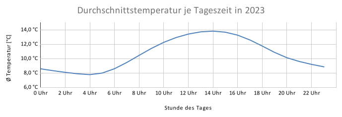
As the outdoor temperature rises, the heat pump can obtain more energy from the ambient air. As shown in the following diagram, the average outdoor temperature in Germany is highest in the early afternoon (data from energy-charts.info). It therefore makes sense to schedule domestic hot water production for the early afternoon between 1 and 3 p.m.
For this purpose, you can use the Auto mode selection with, for example, 4 time programs and 2 modes:
- 1–5 p.m. = preferred time → Eco
- Start temperature: 41 °C
- Stop temperature: 48 °C
- 5–9 p.m. = acceptable time → Eco+
- Start temperature: 33 °C
- Stop temperature: 40 °C
- 9 p.m.–8 a.m. = unacceptable time → Off
- 8 a.m.–1 p.m. = acceptable time → Eco+
- Start temperature: 33 °C
- Stop temperature: 40 °C
In this example, domestic hot water is produced between 1 and 5 p.m. if its temperature has fallen below 41 °C. If it falls below the threshold of 33 °C in the hours before or after, it is heated during the still acceptable morning or evening hours. It is not heated at night.
The settings above only work well if you draw approximately 7–14 °C from the domestic hot water tank on typical days. On these typical days, domestic hot water production should then fall within the preferred time. However, if your daily consumption is higher, you should shift the Eco stop temperature upward accordingly. If your daily consumption is lower, you should adjust the Eco stop temperature so that domestic hot water production occurs every other noon. You can check the current domestic hot water temperature either on the local control unit’s start screen, in the app or via a smart home system. At this point, I would like to emphasize once again that with such low water temperatures, you must either ensure weekly thermal disinfection or complete water replacement in all pipes within a few days [bwp].
The setting described above can also make sense for owners of photovoltaic systems and in terms of the energy transition, because the highest PV yield in Germany can generally be expected around 1 p.m. (see energy-charts.info). Those who own a PV system can go one step further and optimize domestic hot water production using surplus PV power. The comfort mode not used in the settings mentioned above is used for this purpose. You can find further details on implementation, for example, in the guide for evcc.
High Temperature Losses
What should you do in the event of high domestic hot water temperature losses?
I regularly receive messages from readers who have to produce domestic hot water several times a day even though they have implemented the optimizations mentioned above. We also recently had this problem from one day to the next, although it had worked without problems for more than a year beforehand. In our case, it was caused by limescale deposits in the check valve in the domestic hot water circulation pump, which fortunately then cleared itself. For other readers, it was caused by the continuously running circulation pump. More on this in the next chapter. For a third group, it was caused by a missing thermosiphon in the domestic hot water pipe, which the heating contractor then had to retrofit. In all three cases, domestic hot water flows continuously through the pipe and loses heat to the cold pipes and walls.
But when are domestic hot water losses actually considered high?
According to the specification, our 277-liter domestic hot water tank has a heat loss of 67 W. This means that the domestic hot water in the tank loses 67 watts or 0.21 kelvin per hour. A domestic hot water temperature of 65 °C and an ambient temperature of 20 °C are usually assumed for this. After one day, the domestic hot water tank therefore loses approximately 5 K, and the water at 65 °C has cooled to 60 °C.
Mathematical derivation of domestic hot water losses
With a domestic hot water temperature of 65 °C in the 277 l tank and an ambient temperature of 20 °C, the following equation results in a temperature drop of approximately 0.21 K per hour:
\[ \Delta T = \frac{P \cdot t}{c \cdot m} = \frac{67\,\text{W} \cdot 3600\,\text{s}}{4182\,\frac{\text{J}}{\text{kg}\cdot\text{K}} \cdot 277\,\text{kg}} \approx 0{,}21\,\text{K} \]
\(\Delta T\) = temperature change in kelvin (K)
\(P\) = power loss in watts (W)
\(t\) = period in seconds (s)
\(c\) = specific heat capacity of water = 4182 \(\frac{J}{kg \cdot K}\)
\(m\) = mass of the water in kilograms (kg)
However, if the domestic hot water temperature is lower, the power loss is also lower. It decreases proportionally with the difference between the temperatures. At a domestic hot water temperature of 45 °C, it is approximately 37 W or 0.11 K per hour:
Mathematical derivation of reduced domestic hot water losses
\[
P_{neu} = P_{Norm} \cdot \frac{T_{Wasser,neu} - T_{Umgebung}}{T_{Wasser,Norm} - T_{Umgebung}} =
\]
\[ 67\,\text{W} \cdot \frac{45\,\text{°C} - 20\,\text{°C}}{65\,\text{°C} - 20\,\text{°C}} = 67\,\text{W} \cdot \frac{25\,\text{K}}{45\,\text{K}} \approx 37\,\text{W} \]
For our case, this results in a temperature decrease of 0.11 K per hour:
\[ \Delta T = \frac{37\,\text{W} \cdot 3600\,\text{s}}{4182\,\frac{\text{J}}{\text{kg}\cdot\text{K}} \cdot 277\,\text{kg}} \approx 0{,}11\,\text{K} \]
In reality, we are close to this calculated value. In fact, we have a temperature loss of 0.16 K per hour when we draw no water and the circulation pump is not running. The gravity circulation caused by our blocked check valve resulted in an additional temperature loss of 0.33 K per hour. Each year, this results in additional costs of just under €100 at an electricity price of 32 cents/kWh.
Mathematical derivation of the costs
Thermal loss per hour:
\[ Q_{h} = 4182\,\frac{\text{J}}{\text{kg}\cdot\text{K}} \cdot 277\,\text{kg} \cdot 0{,}33\,\text{K} \approx 382\,\text{kJ} \]
Thermal loss per year:
\[ Q_{Jahr} = \frac{382\,\text{kJ} \cdot 8760\,\text{h}}{3.600\,\frac{\text{kJ}}{\text{kWh}}} \approx 930\,\text{kWh}_{\text{th}} \]
Heat pump electricity consumption with a seasonal performance factor of 3:
\[ E_{el} = \frac{Q_{Jahr}}{JAZ} = \frac{930\,\text{kWh}_{\text{th}}}{3} \approx 310\,\text{kWh} \]
Keeping an eye on the domestic hot water temperature loss can therefore certainly be financially worthwhile.
Domestic Hot Water Circulation
If water remains in the pipe for a longer period, it cools down. To be greeted with hot water immediately when turning on the shower or faucet, so-called circulation pipes were installed in many houses in the past. With the help of this additional pipe, hot water is circulated from the domestic hot water tank, which is often located in the heating basement, to the other floors. This means that less water is wasted by unnecessarily running down the drain until hot water finally reaches the faucet or shower. At first, this sounds sensible as a way to conserve the valuable resource of water.
The problem, however, is that circulating hot water through the pipes causes heat energy to be lost to the colder masonry. In winter, one could argue that this additionally heats the house and therefore no energy is lost. However, since domestic hot water is generally at a higher temperature than the heating water and therefore required more electrical energy to produce, this wastes considerable potential.
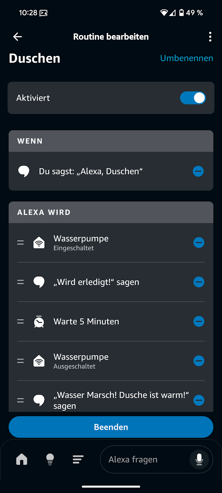
A logical conclusion would be simply to switch off the circulation pump. However, this is not a good idea because of the risk of Legionella. A first optimization is to reduce the circulation pump’s operating time in the heat pump settings. Alternatively, you can have the circulation pump connected to its own power outlet. You can then use a programmable plug adapter, e.g. from Shelly, which activates circulation for 5 minutes at times when it is needed, e.g. in the morning and evening. This saves water while also reducing the energy loss from circulation to a minimum.
If you wish, you can go one step further and switch on the plug adapter when domestic hot water is needed using a Shelly button or an Amazon Alexa routine. You then simply press the button or say “Alexa, shower” to start the circulation pump for 5 minutes.
Cycling Behavior
Using the configured heating curve, the heat pump determines the required target flow temperature for the current/damped outdoor temperature. Ideally, the actual flow temperature in the heating circuit (T0) would always follow the target flow temperature exactly. However, especially during the transitional period with comparatively high outdoor temperatures, this is not always possible because modulation cannot reduce the output arbitrarily far. Depending on the model, the limit is between 12% and 25% of maximum output. If too much heat is still being produced, the heat pump switches off. It switches off when the measured flow temperature exceeds the target flow temperature by 4 K. If the measured flow temperature falls approximately 2 K below the target flow temperature, the heat pump starts again.
The following diagram shows that at 10:32 a.m. the measured flow temperature T0 exceeds the target flow temperature by 4 K. The heat pump switches off. The measured flow temperature then drops until, at 12:22 p.m., it is approximately 2 K below the target flow temperature. The heat pump starts again.

This cycling behavior cannot be prevented during the transitional period.
However, it should not occur too frequently, because the compressor must first be brought into operating mode after starting, which reduces efficiency, and every unnecessary start increases wear.
You can retrieve the number of compressor starts either on the control panel in the service menu under Info → Wärmepumpe → Statistik or in the app.
There you can also see the compressor operating hours, and if you divide the two values, you obtain the average length of a cycle.
For me, this is currently 6.5 hours per cycle.
If your value is very low, e.g. less than 1, you can try the following optimizations:
- Set a minimum flow temperature:
By setting the minimum flow temperature in the service menu under
Anlageneinstellungen→Heizung/Kühlung→Heizkreis 1→Heizen→Minimale Vorlauftemperatur, you ensure that the target flow temperature does not fall below the set value even at higher outdoor temperatures. If the minimum flow temperature were set to 28 °C, the yellow line in the image above would not continue falling at 10:30 a.m. This would prevent the switch-off threshold from being reached and the heat pump would continue running. However, this naturally causes the room temperature to rise and you consume unnecessary electricity. - Alternatively or additionally, you can try to accept the cycling but reduce the number of cycles by using the room temperature night setback. This allows you to significantly reduce the room temperature for several hours, which will probably force the heat pump to switch off. The flow temperature will then probably have fallen significantly, and the heat pump will need several operating hours without cycling to reach the target flow temperature again. Fluctuating room temperatures may reduce comfort.
Naturally, the best approach is to make sure when purchasing the heat pump that it is not oversized, so that modulation is largely sufficient even during the transitional period.
Heating Curve and Hydronic Balancing
We now move from domestic hot water to optimizing the heating system. As with domestic hot water, it is essential that the flow temperature is just low enough for the rooms to become only as warm as necessary. The individual room controls (IRC) or radiator thermostats should not regulate the room temperature by cycling, i.e. by constantly opening and closing the water supply—similar to a car that constantly accelerates to maximum speed and then brakes to a standstill again instead of driving at a constant speed. The aim is therefore for the rooms to be supplied continuously with the minimum necessary water temperature. The heat pump then only needs to heat to the minimum flow temperature that is currently necessary to heat all rooms to a comfortable temperature.
This minimum flow temperature and the fine adjustment of the flow rate are achieved through so-called hydronic balancing. The following 6-step guide to hydronic balancing comes from Haustechnikdialog.de:
- Prepare the system
With underfloor heating, the IRCs should be deactivated during balancing or the actuators should be removed. All restrictions on the heating circuit manifolds should be fully opened. For radiators, the thermostat heads should be fully opened or temporarily removed. The aim is for the IRCs/thermostats not to intervene during the measurement phase. Room temperatures should be determined solely by the heating curve and flow rate. - Lower the heating curve roughly
Wait at least 1–2 days after preparation. If all regularly heated rooms are warmer than desired afterward, the heating curve is probably too high. Now lower the heating curve step by step. After each change, wait long enough again; with slow underfloor heating, ideally around 48 hours. Continue reducing the heating curve until the first room just fails to reach its desired temperature. This room is your reference room. It will not be restricted further during the balancing process. - Readjust the reference room
Raise the heating curve slightly so that the reference room reliably reaches its desired temperature. The heating curve is now initially set as low as possible. All rooms that are still too warm are receiving too much flow and will subsequently be restricted individually. - Gradually restrict rooms that are too warm
Start with the room that is warmest relative to the desired temperature. Restrict the flow there only slightly and then wait at least another 1–2 days. If the room is still too warm afterward, restrict the flow slightly again. If it becomes too cold, open the flow somewhat again. - Check the heating curve after each restriction round
Restricting one room changes the distribution of heating water in the rest of the system. The reference room may therefore become somewhat warmer afterward. For this reason, check the reference room after each restriction round. If it is too warm, the heating curve can be lowered slightly further. Then check the rooms that have already been adjusted again and correct them slightly if necessary. - Repeat room by room
Repeat this procedure until all regularly heated rooms reach their desired temperature and the heating curve is set as low as possible. Hydronic balancing is not a one-time task, but rather a gradual fine adjustment over several cold days or even an entire heating season.
The procedure should be carried out on a cold day with subzero temperatures and little solar radiation. To adjust the heating curve in steps 2 and 5, reduce the flow temperature at the design outdoor temperature (DOT). It should also be noted that it makes no sense for the target temperatures in adjacent rooms to differ greatly. A difference of a few degrees is fine, but if the differences are too large, the cold rooms are simply heated by the warm rooms, and a higher flow temperature is required in the warmer room again.
Before adjusting the heating curve at the DOT, you should set the heating limit temperature. To do this, simply check in autumn at outdoor temperatures of around 15°C at which temperature you stop feeling comfortable in the house. This naturally varies from person to person. To prevent unnecessary cycling, a lower heating limit temperature is preferable.
Balancing Flow Rates
To understand the balancing of flow rates between the primary circuit and heating circuit, it is necessary to examine the control of the circuits in somewhat more detail. In the primary circuit, the target variable is the temperature difference dT between the flow (TC3) and return (TC0), the so-called temperature difference. The temperature difference is achieved by controlling the flow rate of the speed-controlled primary circuit pump (PC0). If the temperature difference is too low, PC0 reduces the flow rate so that the water can absorb more heat in the heat exchanger and the temperature difference increases. If the temperature difference is too high, PC0 increases the flow rate.
In the heating circuit, on the other hand, the differential pressure is set. The temperature difference results from the heat output of the radiators or underfloor heating and therefore cannot be set. The set differential pressure ensures a constant flow rate in the heating circuit. This naturally only applies if the valve position at the radiators or underfloor heating remains unchanged. If the thermostat changes the valve position, the resistance changes and, to ensure a constant differential pressure, PC1 must adjust the flow rate. For better efficiency and stability, the thermostats should therefore always be as open as possible, and the flow rate should be set permanently at the valve base or flow regulator, as described under Heating Curve and Hydronic Balancing.
By default, the Bosch CS 5800/6800i and Buderus WLW 176/186i have a primary circuit temperature difference of 4.5 K for underfloor heating and 7.5 K for radiators, as well as a differential pressure of 250 mbar stored.
If now
- the primary circuit has a higher flow rate than the heating circuit can accept—in this case, the primary circuit draws warm water directly back into the return and the heat pump switches off—or
- the primary circuit provides a lower flow rate than the heating circuit draws—in this case, the heating circuit transports colder water from its return directly back into its flow. This would cause the temperature in the heating circuit to drop. However, the heat pump control ensures that the flow temperature (T0) in the heating circuit follows the target flow temperature from the heating curve. The control achieves this by increasing the flow temperature in the primary circuit (TC3). This requires more output and consequently reduces efficiency.
Interactive Circuit Simulator
The following simulator lets you visually understand the three circuits (refrigerant circuit, primary circuit and heating circuit).
Caution: The simulator is only an initial, very simplified attempt to simulate the heat pump processes and certainly still contains some errors. If you have specific suggestions for improvement, feel free to create a pull request.